Research - (2022) Volume 10, Issue 3
Associating Torque to Abutment Screw Loosening Using Computer Aided Designing and Finite Element Analysis
*Correspondence: Shaiq Gajdhar, Department of Prosthodontics, A.C.P.M. Dental College, India, Email:
Abstract
Background: The dental implant abutment connection plays a very crucial role in the quality of the stress distribution, and, over the years, different designs were proposed. Most common complication after the dental implant treatment is abutment screw loosening that adversely affects the outcomes of implant rehabilitation. Therefore, this study was aimed to correlate the abutment screw loosening at four different torques and to study the stress and deflection pattern of the abutment screw using three - dimensional finite element analysis. Methods: Three dimensional computer aided designed (CAD) models were generated, which were having a detailed geometry of the implant, abutment, abutment screw, surrounding hard and the soft tissues of the mandibular jaw. The abutment screw was than torqued at 10 Ncm. One point load of 170 N was then applied 30o oblique to the long axis of implant. The abutment screw loosening was determined for each of the models at the specified load (170N and 185N) by calculating the amount of preload remaining in the abutment screw and remaining torque (T) after the load application. Results: After the load application the screw loosening was observed in all the models. A minimal screw loosening of 0.67o was observed for the models which were torqued at 10 Ncm and subjected to 175 N of Load. A maximum screw loosening in this study was 0.75o which was observed with the models that were torqued at 6 Ncm and subjected to 185 N of load; the abutment without screw tightening torque (0 Ncm) also showed a screw loosening of 0.71o. With the similar load application of 185 N as the torque of 10 Ncm applied, the abutment screw showed a screw loosening by 0.73o. Conclusions: CAD Designed models and finite element method to apply load can be an effective way to determine the abutment screw loosening. Within the limitations of the study it can be concluded that the abutment screw loosening increases with the increase in the load applied. Also there are more chances of abutment screw to be loosened with the decrease in the torque values.
Keywords
Implant, Abutment, Finite Element Analysis (FEM) Analysis, Computer Aided Designing.
Introduction
Common complications during dental implant rehabilitation like implant and prosthetic component fracture and prosthetic abutment screw loosening adversely affect the acceptance and progress of implant dentistry. Prosthetic design and materials of implant, as well as the tolerance of the connection between the implant and its corresponding prosthetic component, have continued to improve. Component fracture and screw loosening, predominantly for the single tooth application, are common concerns of commercially available implant designs [1]. Replacement of single lost molar with only one implant represents a biomechanical challenge. Lateral forces create a bending moment relative to the implant at its marginal bone, and axial forces introduce bending if offset from the implant axis in a mesiodistal or buccolingual direction. In contrast with the fact that occlusal forces are at their greatest in the molar region, this leads to possible elevated stress on components as well as bone [2,3]. The screw is a crucial part of implant prosthesis. Screw loosening can lead to displacement of prosthesis and further cause loss of the function. It may also cause poor fitting of implant abutment interface, leading bio - mechanical complications like micro leakage of bacteria, fractures of the screw and / or the framework.3 Inadequate preload, loss of preload subsequent to insufficient initial torquing, deformation of screw, wear of the screw, over - loading, and micro - movements due to functional loading may be responsible for screw loosening [4].
The objectives of the study were to correlate the abutment screw loosening at four different torques and to study the stress and deflection pattern of the abutment screw using three - dimensional finite element analysis.
Methods
Finite element model
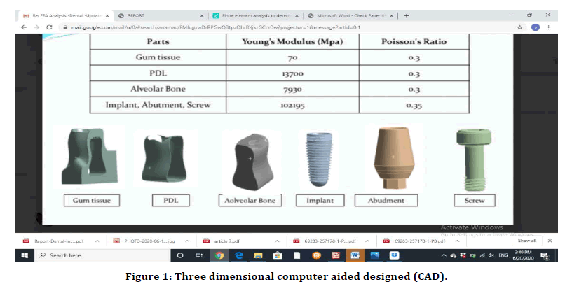
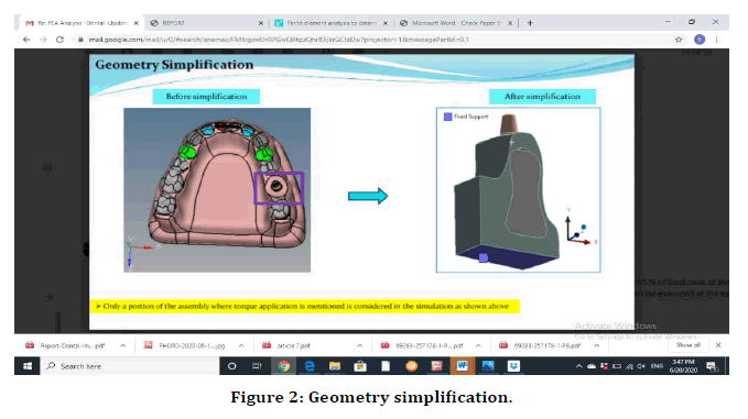
Three dimensional computer aided designed (CAD) models were generated, which were having a detailed geometry of the implant, abutment, abutment screw, surrounding hard and the soft tissues of the mandibular jaw (Figure 1). Using the predefined material properties (Table 1) of each of the components, a complete lower jaw model was generated. The designed models of the implant, abutment and abutment screw were embedded in the mandibular 1st molar area and all the components assembled. The Abutment affixed to the implant body using abutment screw (Figure 2).

Figure 1. Three dimensional computer aided designed (CAD).
| Components | Young’s Modulus(MPA) | Poisson’s Ratio |
|---|---|---|
| Implant | 102195 | 0.35 |
| Abutment Screw | 102195 | 0.35 |
| Abutment | 102195 | 0.35 |
| Alveolar Bone | 7930 | 0.3 |
| PDL | 13700 | 0.3 |
| Gums | 70 | 0.3 |
Table 1: Predefined material properties.

Figure 2. Geometry simplification.
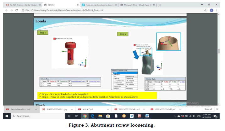
The abutment screw was than torqued at 10 Ncm. One point load of 170 N was then applied 30o oblique (Figure 3) to the long axis of implant. The area of load application was kept most distal side of the implant abutment and the direction of the load application was from the lingual side of the abutment. In the similar way other models were subjected to 0 Ncm, 6 Ncm and 10 Ncm torques and a load of 185 N was then applied respectively to the individual models. The area of load application was similarly kept most distal side of the implant abutment and the direction of the load application was from the lingual side of the abutment.

Figure 3. Abutment screw loosening.
The abutment screw loosening was determined for each of the models at the specified load (170N and 185N) by calculating the amount of preload remaining in the abutment screw and remaining torque (T) after the load application using the below mentioned equations. The screw loosening in (o) was also calculated.
PreLoad=100 / (abutment screw diameter* torque coefficient).
Torque(T)=Preload*Torque Factor*Abutment screw diameter.
Results
As described, the designed models of the implant, abutment and abutment screw were embedded in the mandibular 1st molar area and all the components assembled. The Abutment affixed to the implant body using abutment screw, was than torqued at 10 Ncm and one point load of 170 N was then applied 30 o oblique to the long axis of implant. The area of load application was kept most distal side of the implant abutment and the direction of the load application was from the lingual side of the abutment. The abutment screw loosening was than calculated by determining the amount of preload remaining. In the similar way other models were subjected to 0 Ncm, 6 Ncm and 10 Ncm torques and a load of 185 N was then applied respectively to the individual models. The area of load application was similarly kept most distal side of the implant abutment and the direction of the load application was from the lingual side of the abutment.
Although by the action of the load application the screw loosening was observed in all the models. A minimal screw loosening of 0.67° was observed for the models which were torqued at 10 Ncm and subjected to 175 N of Load. A maximum screw loosening in this study was 0.75° which was observed with the models that were torqued at 6 Ncm and subjected to 185 N of load; the abutment without screw tightening torque (0 Ncm) also showed a screw loosening of 0.71°. With the similar load application of 185 N as the torque of 10 Ncm applied, the abutment screw showed a screw loosening by 0.73°. The results were calculated and summarized in Table 2.
| Torque (Ncm) | Bolt pre load (N) | Load (N) | Bolt pre load remaining (N) | Abutment Screw loosening and different tightening torques | Location of force | ||
|---|---|---|---|---|---|---|---|
| Remaining Torque (Ncm) | Screw Loosening (O) | 30 degrees from lingal side of 1 st molar above the abutment (Distal part) | |||||
| 0 | 0 | 185 | - 17.584 | - | 0.71 | ||
| 6 | 246.9136 | 185 | 228.42 | 5.5 | 0.75 | 91.66 | |
| 10 | 411.5226 | 185 | 393.94 | 9.57 | 0.73 | 95.7 | |
| 10 | 411.5226 | 170 | 394.83 | 9.59 | 0.67 | 95.9 | |
Table 2: Torque.
Discussion
The objectives of this study was to correlate the abutment screw loosening of computer aided designed (CAD) models at different torques when exposed to load through a three dimensional finite element analysis. In a study conducted previously by Barbosa et.al. to evaluate abutment screw loosening, the values of the torques applied and detorques were measured with a digital torque wrench on physically manufactured components [5]. In another study counducted by Siamos et al. all the components were physically manufactured followed by evaluating the loosening torque values to determine the abutment screw loosening [6]. Wierszycki et al. in their study concluded that, for screw loosening simulation, the modeling of tightening is a crucial task. It has to be carried out in such a way that describes a real physical process as much as possible. Only a 3D modeling allows a full simulation of kinematics of the implant, describing the multi - axial state of stress and, in consequence, the possibility of screw loosening [7]. Similarly in our study to simulate a real physical process as much as possible, computer aided designed (CAD) models were fabricated & torque at 0Ncm, 6Ncm and 10Ncm which were than exposed to load of 170 N and 185 N through a three dimensional finite element method. The torque to tighten the abutment screw that was used in the study were 0Ncm, 6Ncm and 10Ncm. In a study by Kanawati et al. Measurement of clinicians' ability to hand torque dental implant components a maximum torque values for all participants ranged from 11 Ncm to 38 Ncm [8]. So in our study the torque values were taken lesser than the maximum hand torque values that can be achieved by a clinician. The models in the study were subjected to a load of 170 and 185 N at an angle of 30o oblique to the long axis of implant. In a study conducted by Kose OD et.al 30° loading angle, which is close to the tubercle slope of posterior teeth was used [9]. The same loading angle and location is also recommended in the ISO 14801 protocol10, which was developed for evaluating the mechanical resistance of dental implant materials. In the present study, as the crown was not used the load application was done most distal part of the abutment. The load application was single point load from the lingual side 30o oblique to the long axis of implant. As seen in the results by the action of the load application the screw loosening was observed in all the models. A minimal screw loosening of 0.67o was observed for the models which were torqued at 10 Ncm and subjected to 170 N of Load, around 4 % reduction in the remaining torque readings was observed. This might be because the load used in this case was 8 % lesser than the other models. A maximum screw loosening in this study was 0.75° which was observed with the models that were torqued at 6 Ncm and subjected to 185 N of load. Remaining torque was around 8 % lesser than the initial torque values. The abutment without screw tightening torque (0 Ncm) also showed a screw loosening of 0.71°, which was calculated by a negative value in the amount of preload remaining in the abutment screw (-17.58N). With the similar load application of 185 N as the torque of 10 Ncm applied, the abutment screw showed a screw loosening by 0.73°. The remaining torque was around 6 % lesser than the initial torque values.
Conclusion
As described in the present study CAD Designed models and finite element method to apply load can be an effective way to determine the abutment screw loosening. Within the limitations of the study it can be concluded that the abutment screw loosening increases with the increase in the load applied. Also there are more chances of abutment screw to be loosened with the decrease in the torque values. Further investigations are recommended to see the effect of location and angulation of load application. Other factors including crown to implant ratio causing screw loosening can also be investigated using CAD Designed models and finite element method to apply load on the models as described in the present study.
Conflicts of Interest
The authors declared no potential conflicts of interest with respect to the research, authorship, and / or publication of this article.
References
- Boggan RS, Strong JT, Misch CE, et al. Influence of hex geometry and prosthetic table width on static and fatigue strength of dental implants. J Prosthet Dent 1999; 82:436-40.
- Elfadaly LS, Khairallah LS, Al Agroudy MA. Peri-implant biomechanical responses to standard, short-wide, and double mini implants replacing missing molar supporting hybrid ceramic or full-metal crowns under axial and off-axial loading: An in vitro study. Int J Implant Dent 2017; 3:31.
- Balshi TJ, Hernandez RE, Pryszlak MC, et al. A comparative study of one implant versus two replacing a single molar. Int J Oral Maxillofac Implant 1996; 11.
- Kim SK, Koak JY, Heo SJet al. Screw loosening with interchangeable abutments in internally connected implants after cyclic loading. Int J Oral Maxillofac Implants 2012; 27:42-7.
- Barbosa GS, Silva-Neto JP, Simamoto-Júnior PC, et al. Evaluation of screw loosening on new abutment screws and after successive tightening. Brazilian Dent J 2011; 22:51-55.
- Siamos G, Winkler S, Boberick KG. The relationship between implant preload and screw loosening on implant-supported prostheses. J Oral Implantol 2002; 28:67-73.
- Wierszycki M, Kąkol W, Łodygowski T. The screw loosening and fatigue analyses of three dimensional dental implant model. In ABAQUS Users’ Conference 2006.
- Kanawati A, Richards MW, Becker JJ, et al. Measurement of clinicians' ability to hand torque dental implant components. J Oral Implantol 2009; 35:185-188.
- Dincer Kose O, Karataslı B, Demircan S, et al. In vitro evaluation of manual torque values applied to implant-abutment complex by different clinicians and abutment screw loosening. Bio Med Res Int 2017; 2017.
Indexed at, Google Scholar, Cross Ref
Indexed at, Google Scholar, Cross Ref
Indexed at, Google Scholar, Cross Ref
Indexed at, Google Scholar, Cross Ref
Indexed at, Google Scholar, Cross Ref
Indexed at, Google Scholar, Cross Ref
Author Info
Department of Prosthodontics, A.C.P.M. Dental College, Dhule, Maharashtra, IndiaReceived: 21-Feb-2022, Manuscript No. JRMDS-22-55090; , Pre QC No. JRMDS-22-55090 (PQ); Editor assigned: 23-Feb-2022, Pre QC No. JRMDS-22-55090 (PQ); Reviewed: 02-Mar-2022, QC No. JRMDS-22-55090; Revised: 07-Mar-2022, Manuscript No. JRMDS-22-55090 (R); Published: 14-Mar-2022
