Research - (2021) Volume 9, Issue 2
Biomechanical Analysis of Orthodontic Correction of Buccally Malposed Canine: A Finite Element Analysis
Muthanna Ibraheem Ali1, Iman I Al Sheakli2* and Salah R Al Zaidee3
*Correspondence: Iman I Al Sheakli, Department of Orthodontics, College of Dentistry, University of Baghdad, Iraq, Email:
Abstract
Canines are important and unique teeth for both esthetic and function. It is the most tooth that erupt in malposed position. The buccaly malposed canine is one of the most common condition in orthodontic practice. The aim of this study is to evaluate the response of canine and maxillary teeth to different magnitudes and directions of orthodontic force. The finite element method were used in current work. DICOM data processed by image processing software (Mimics Medical 2018), for generation of 3D volume that managed by computer aided design software (SolidWorks software), for reconstruction 3D model and to align all parts in final assembly. The model exported to finite element analysis software (Abaqus CAE software) and apply two load scenarios. Load scenario I include tipping force extend between canine and first molar, Load scenario II include extrusion force extend between canine and main arch wire. Then we run finite element processing. Result: In load scenario I, the canine have uncontrolled palatal and lingual tipping with distal-in rotation. The first molar have bodily mesial and buccal movement with intrusion. Small anterior displacement in central and lateral incisor, and first and second premolar. Scenario II show extensive extrusion of canine and severe intrusion of lateral incisor and moderate intrusion of central incisor. First and second premolar and first molar were not affected. Discussion: Distal tipping of canine lead to intrusion of first molar and proclination of incisors (increase overjet) even with use heavy gauge archwires. Extrusion of canine cause extensive intrusion of lateral incisor even with use maximum anchorage.
Keywords
Orthodontics, Malposed canine, Central and lateral incisors, Permanent canine, Finite element
Introduction
Human beings have four pointed teeth one on each side of the dental arch called canine or cuspid. Each canine represents the third tooth from the median line after the central and lateral incisors forming the key stone or the corner stone of the dental arch [1]. They are the longest teeth in the mouth; the crowns are usually as long as those of the maxillary central incisors and the single roots are longer than those of any of the other teeth. The middle labial lobes have been highly developed incisally into strong, well-formed cusps. The shape and position of the canines contribute to the guidance of the teeth into the intercuspal position by “canine guidance [2].
Importance: The positions and forms of the permanent canine and their anchorage in the bone, along with the bone ridge over the labial portions of the roots, called the canine eminence, have a cosmetic value. They help form a foundation that ensures normal facial expression at the corners of the mouth. Loss of all of these teeth makes it extremely difficult, if not impossible, to make replacements that restore that natural appearance of the face for any length of time. It would therefore be difficult to place a value on the canines, and their importance is manifested by their efficiency in function, stability, and aid in maintaining natural facial expression. In function, the canines support the incisors and premolars, since they are located between these groups. The canine crowns have some characteristics of functional form, which bears a resemblance to incisor form and also to the premolar form [3].
Management: There are many techniques to align the malposed upper caninereported three categories of management, these are: (A) Removable appliance, (B) Fixed appliance, and (C) Canine extraction.
Removable appliance: It is used when only tipping movement is required, which is found in 51% of cases of Iraqi orthodontic patient. These appliance are used when the buccaly malposed canine was mesially inclined and space was available naturally or orthodontically prepared [4].
Fixed appliances: This is a more complicated appliance and can be used only by orthodontists that’s why it is beyond the level of general dental practitioner, it was used when root movement was needed especially in vertically or distally angulated canines with the use of full arch multi bands or brackets or by sectional arch wires the alignment was accomplished [5,6].
The engagement of a continuous arch wire in largely displaced teeth, whether using selfligating brackets or conventional brackets, produces both an ineffective force system and greater side effects, and, a stiff main arch wire with an auxiliary spring, such as a cantilever spring or NiTi overlay, is recommended when leveling a severely displaced canine [7].
Finite Element Method (FEM) is a mathematical method where in the shape of complex geometric objects and their physical properties are computer constructed. Finite Element Analysis (FEA) is a modern tool for numerical stress analysis, which has the advantage of being applicable to solids of irregular geometry that contain heterogeneous material properties [8].
Finite element (FE) method models have shown advantages in the biomechanical analysis of orthodontic tooth movement [9,10] which have been used in several studies for biomechanical research related to orthodontic tooth movement, such as torque control [11,12] Sliding mechanics in space closure for labial orthodontics [13]. Use of microscrews [14,15] molar distalization [16], arch expansion [17] and yet there are rare studies focusing on biomechanical research for lingual orthodontics.
Material and Method
Typical human subject. Due to symmetry, only half of the maxilla was built. The model shows the buccally malposed canine and the adjacent teeth, periodontal ligament (PDL), alveolar bone, as well as the orthodontic appliance include brackets and arch wire (Figure 1).
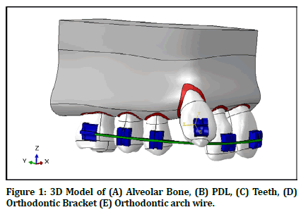
Figure 1. 3D Model of (A) Alveolar Bone, (B) PDL, (C) Teeth, (D) Orthodontic Bracket (E) Orthodontic arch wire.
The DICOM file consisted of Cone Beam Computerized Tomography (CBCT) images of an adult male patient with skeletal class 1 and a complete definition set without any craniofacial anomalies.
3D segmentation of the DICOM data
The DICOM file was imported to image processing software (3D modeling software) for construction of a 3D model of the teeth and alveolar bone. The present study uses Mimics Medical 2018 (MIMICS, (Materialize, N.V., 2013. 3D Medical Image Processing Software. Materialize Mimics, Belgium) for this purpose.
In MIMICS Software we apply thresholding tool which is process of segmentation of the DICOM image based on the Hounsfield scale that the segmentation object (visualized by a colored mask) will contain only those pixels that have Hounsfield scale between or equal to the selected limits. The tissue with density higher and lower than that of enamel, dentin and bone will automatically be erased (Table 1).
| Material | Young's modulus | Poisson's ratio |
|---|---|---|
| Tooth | 20, 000 | 0.30 (20, 21, 22, 23) |
| PDL | 0.13 | 0.45(24, 25, 26) |
| Alveolar Bone | 13, 800 | 0.30 (20, 27) |
| Stainless Steel | 200 | 0.30 (24, 28) |
Table 1: Material properties.
The tissue of the teeth was segmented semiautomatically so the roots were isolated from the surrounding tissue by setting the range of the greyscale value to the minimum limit of the threshold is (292 Hounsfield Unit), and maximum limit of the threshold is (3095 Hounsfield Unit).
Reconstruction of the tooth, PDL and alveolar bone
Imports the geometry as Steriolethograph (STL) body to SolidWorks software (Solidworks 2018, Dassault Systèmes, Vélizy-Villacoublay, France) to complete reconstruction the tooth and alveolar bone. The PDL was built by using “surface offset” for the roots with 0.2 mm thickness accordance with previous studies (Figure 2).
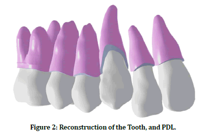
Figure 2. Reconstruction of the Tooth, and PDL.
Reconstruction of orthodontic hard-ware
The bracket's modeling was based on manual measurement of the edgewise bracket of a 0.022 inch MBT bracket of central incisor from IOS comp. (International Orthodontic Services, Stafford, Texas, USA). The dimensions of slot were 0.022 inch (0.55 mm) in width (vertically) and 0.025 inch (0.63 mm) in depth (horizontally) (Figure 3). Each structure had been saved in the Parasolid format and exported to Abaqus software.
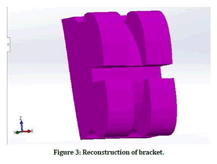
Figure 3. Reconstruction of bracket.
Material properties
All the materials in present study were considered homogeneous which means all points in the material have same elastic properties. The material also considered linearly elastic there was a linear relationship between strain and stress, and isotropic which means any point of the material had the same elastic properties in all directions [18]. So, only the Young's modulus (or modulus of elasticity), the shear modulus, and the Poisson's ratio were need to be determined for finite element analysis [19].
Interactions
In the present study, all interfaces were defined as tie contact because all the teeth (except the canine) were considered to be set with heavy gauge archwire and ligated to each other as one unit.
Boundary condition
In this research, the model has two surfaces with a fixed boundary condition: The first one was a supra-apical horizontal plane at the superior border of the maxilla representing its contact with the bone of the cranium (Figure 4A). The second surface is the central sagittal plane mesial to the central incisor, representing its contact with the opposite halve of the maxilla (Figure 4B). These two surfaces were restricted with zero-displacement and zero-rotation boundary conditions (0 of movement in all six degrees of freedom of the nodes in this area.
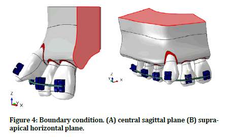
Figure 4. Boundary condition. (A) central sagittal plane (B) supraapical horizontal plane.
Load scenarios
The present study designed to manage the buccally malposed canine by applying two load scenarios based on change in direction, magnitude and point of application of orthodontic force.
Load scenario (Uncontrolled tipping load)
Magnitude: 60 g (=0.6 N) according to the optimum force for orthodontic tooth movement [20,21].
Direction: Extending between the attachment (bracket) on the crown of the buccally malposed canine on the labial surface and the attachment on the first molar (Figure 5). Clinically the load exerted by elastic or coil spring extends from the attachment (bracket) on the labial surface of the crown of the buccally malposed canine to the attachment on the first molar. In Abaqus software, the loads represented by two forces equal magnitude and opposite direction at the same action line. One extends from the bracket on the canine toward the attachment on the first molar, and the second extends from the attachment on the first molar toward the canine's bracket.
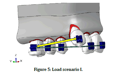
Figure 5. Load scenario I.
Load Scenario (Extrusion Load)
Magnitude: 60 g (=0.6 N) according to the optimum forces for orthodontic tooth movement [20,21].
Direction: Clinically, the load exerted by elastic or coil spring extends from the attachment (bracket) on the labial surface of the crown of the buccally malposed canine to the archwire. In Abaqus software, the loads represented by two forces equal magnitude at the same action line and opposite direction. One extends from the bracket toward the archwire, and the second extends from the archwire toward the bracket (Figure 6).
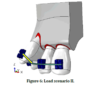
Figure 6. Load scenario II.
The assembled model was managed by the meshing tool of Abaqus software to discretize into a finite number of elements that connected to each other by nodes.
Meshing
In the present study, the models were meshed using ten node tetrahedral elements, (C3D10: 10-node quadratic tetrahedron) The meshing tool in Abaqus software calculates the size and number of elements for each part separately by determining the numerical dimensions of the part and visualizing how these dimensions relate to lines and curves.
Analysis and visualization the results
In the present study, the analysis was performed in static and general step with one second period. The results were saved in the output database and visualized in different means of examination as follows.
Graphical form.
✓ Contour plot.
Banded type of counter plot with Rainbow spectrum where used in current study.
✓ Symbol plot.
A symbol plot with uniform color and constant length arrows and moderate density.
Numerical form
In order to examine the displacement of the tooth depending on the position of the applied force, four points were selected,
✓ Tip point: coronal tips, midpoints of the incisal edges of the central and lateral incisors, the cusp tip of the canine, the buccal cusp tips of the premolars, and the mesiobuccal cusp tips of the molars.
✓ Apex point: the root apex of anteriors, buccal root apex of premolars and mesiobuccal root apex.
✓ Mesial point) the mesial contact points, and
✓ Distal point) the distal contact points.
The displacement of the selected points was represented along with three directions (X-, Y-, and Z-axes). The movements of these four points interpret the movement of the tooth. As well as, the difference between displacements of this points interpret the type of tooth movement, as the difference between displacement of the Tip point and Apex point interpret whether the tooth has bodily, tipping or up righting movement, and the difference between the displacement of the mesial point and the distal point interpret whether the tooth rotated or not. Displacement was measured along the transverse plane (X-axis), sagittal plane (Y-axis) and vertical plane (Z-axis).
Displacement in the transverse plane (X-axis), represents movement in a medio-lateral direction (bucco- lingual direction for posterior teeth or mesio-distal direction for anterior) where a positive (+) sign indicated displacement toward midline (lingual movement for posterior teeth and mesial movement for anterior teeth) and a negative (-) sign indicated lateral displacement away from the midline (buccal movement for posterior teeth or distal movement for anterior teeth).
Displacement in the sagittal plane (Y axis), represents movement in the anterio-posterior direction where a positive (+) sign indicated displacement in the posterior direction (distal movement for posterior teeth and palatal movement for anterior teeth), and a negative (-) sign indicated anterior displacement (mesial movement for anterior teeth and labial movement for anterior teeth). Displacement in the vertical plane (Z axis), represents movements in a vertical direction where a positive (+) sign indicated apical displacement (intrusive movement for teeth) and a negative (-) sign indicated an. occlusal displacement (extrusive movement for all teeth).
Results
Initial displacement of teeth in finite element analysis
Orthodontic tooth movement was assumed to occur by accumulating the initial displacement of teeth produced by elastic deformation of the PDL.
Scenario
Depending on the magnitude and direction of displacement of individual tooth, the teeth of the sample were divided into four groups (1) Central and lateral (2) Canine (3) First and, second premolar (4) First molar. For each group, we measure magnitude of displacement, direction of displacement and type of tooth movement.
Central and lateral incisors
Displacement in the sagittal plane (ΔY), the central and lateral incisors was displaced in the forward direction (proclintation) in magnitude (ΔY=-0.07 to -0.2 μm).
Displacement in the transverse plane (ΔX), the central and lateral incisors were displaced toward the midline (mesial displacement) in magnitude (ΔX=0.04 to 0.1 μm)
Displacement in the vertical plane (ΔZ), the central and lateral incisors were displaced in occlusal direction (extrusion) in magnitude (ΔZ=- 0.01 to -0.05 μm). The type of tooth movement of the central incisor was bodily movement. (Minor difference in displacement between tip point and apex point) (Figures 7 and 8), (Table 2).
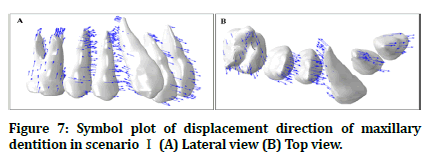
Figure 7. Symbol plot of displacement direction of maxillary dentition in scenario Ⅰ (A) Lateral view (B) Top view.
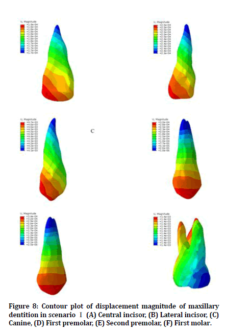
Figure 8. Contour plot of displacement magnitude of maxillary dentition in scenario Ⅰ (A) Central incisor, (B) Lateral incisor, (C) Canine, (D) First premolar, (E) Second premolar, (F) First molar.
| Points. A | Displacement (μm) | |||||||||||||||||
|---|---|---|---|---|---|---|---|---|---|---|---|---|---|---|---|---|---|---|
| Central incisor | Lateral incisor | Canine | First Premolar | Second Premolar | First Molar | |||||||||||||
| ∆X | ∆Y | ∆Z | ∆X | ∆Y | ∆Z | ∆X | ∆Y | ∆Z | ∆X | ∆Y | ∆Z | ∆X | ∆Y | ∆Z | ∆X | ∆Y | ∆Z | |
| Tip | 0.104 | -0.093 | -0.05 | 0.089 | -0.23 | -0.051 | 0.332 | 4.604 | 0.301 | 0.125 | -0.275 | 0.032 | 0.048 | -0.337 | 0.046 | -0.146 | -0.435 | 1.327 |
| Apex | 0.089 | -0.082 | -0.055 | 0.07 | -0.217 | -0.055 | -0.784 | 3.981 | 0.641 | 0.001 | -0.002 | 0.001 | 0 | -0.003 | 0.003 | -0.145 | -0.44 | 1.328 |
| Mesial | 0.102 | -0.094 | -0.05 | 0.088 | -0.226 | -0.05 | 0.354 | 4.421 | 0.307 | 0.121 | -0.23 | 0.057 | 0.056 | -0.298 | 0.061 | -0.146 | -0.436 | 1.326 |
| Distal | 0.101 | -0.094 | -0.052 | 0.087 | -0.231 | -0.053 | 0.659 | 4.571 | 0.388 | 0.1 | -0.261 | 0.021 | 0.019 | -0.298 | -0.015 | -0.145 | -0.436 | 1.329 |
Table 2: Initial displacement of the selected point in maxillary dentition in X, Y, and Z- planes in scenario 1.
Canine
Displacement in the sagittal plane (ΔY): the canine was displaced in the posterior direction (distal tipping) in magnitude (ΔY=1 to 4 μm).
Displacement in the transverse plane (ΔX), the crown of the canine (that include Tip, Mesial and Distal points) was displaced toward the midline (palatal inclination). The Apex point displaced away from the midline. The type of tooth movement is an uncontrolled tipping movement. The Distal point displaced more than the mesial point that means the canine has distal in rotation.
Displacement in the vertical plane (ΔZ): the canine was displaced in apical direction (intrusion) in small magnitude of (ΔZ=0.1 to 0.6 μm). (Figure 7 and 8), (Table 2).
First and second premolar
First and second premolar show small displacement in all directions.
Displacement in the sagittal plane (ΔY): The crown of first and second premolar (that include Tip, Mesial and Distal points) have forward displacement (mesially) in magnitude (ΔY= 0.1 to 0.2 μm). The Apex point has very small or no displacement. The type of tooth movement is the controlled tipping movement.
Displacement in the transverse plane (ΔX): The crown of first and second premolar (that include Tip, Mesial and Distal points) have a palatal displacement in magnitude (ΔY= 0.1 μm). The Apex point has very small or no displacement. The type of tooth movement is the controlled tipping movement.
Displacement in the vertical plane (ΔZ): The First and second premolar was displaced in apical direction (intrusion) in magnitude (ΔZ=0.01 to -0.06 μm) (Figure 7 and 8), (Table 2).
First molar
Displacement in the sagittal plane (ΔY): The First molar displaced in the forward direction (mesially) in the magnitude of (ΔY=0.2 to 0.4 μm)
Displacement in the transverse plane (ΔX): The First molar displaced in the lateral direction (buccally) in the magnitude of (ΔX=0.1 to 0.2 μm).
Displacement in the vertical plane (ΔZ): The First molar was displaced in apical direction (intrusion) in high magnitude (ΔZ=1.0 μm) (Figure 7 and 8), and (Table 2).
Scenario
In this scenario the Load 1 (60 g=0.6 N) represented by two forces equal magnitude at the same action line and opposite direction. One extends from the bracket toward the archwire and the second extend from the archwire toward the bracket.
Depending on the magnitude and direction of displacement of individual tooth, the teeth of the sample were divided into four groups (1) Central incisor (2) Lateral incisor (3) Canine (4) first premolar, second premolar, and first molar. For each group, we measure magnitude of displacement, direction of displacement and type of tooth movement.
Central incisor
Displacement in the sagittal plane (ΔY): There are very small displacement of central incisor in anterior direction.
Displacement in the transverse plane (ΔX): There are very small displacement of central incisor in lateral direction.
Displacement in the vertical plane (ΔZ): The central incisor displaced in apical direction with magnitude (ΔZ=0.5 to 1 μm) that mean intrusion of central incisor.
The magnitude of apical displacement of central incisor were less than that of lateral incisor, (Table 3), and (Figure 9 and 10).
| Points. E | Displacement (μm) | |||||||||||||||||
|---|---|---|---|---|---|---|---|---|---|---|---|---|---|---|---|---|---|---|
| Central incisor | Lateral incisor | Canine | First Premolar | Second Premolar | First Molar | |||||||||||||
| ∆X | ∆Y | ∆Z | ∆X | ∆Y | ∆Z | ∆X | ∆Y | ∆Z | ∆X | ∆Y | ∆Z | ∆X | ∆Y | ∆Z | ∆X | ∆Y | ∆Z | |
| Tip | -0.684 | 0.14 | 1.677 | -0.749 | 0.13 | 2.888 | 1.158 | 2.091 | -3.316 | -0.005 | -0.197 | 0.06 | 0.053 | -0.143 | 0.006 | 0.046 | -0.133 | -0.002 |
| Apex | -0.573 | 0.208 | 1.649 | -0.597 | 0.034 | 2.816 | 0.909 | 1.603 | -2.657 | 0 | -0.001 | 0.003 | 0.001 | -0.001 | 0 | 0.046 | -0.133 | -0.002 |
| Mesial | -0.672 | 0.143 | 1.658 | -0.742 | 0.128 | 2.871 | 1.13 | 2.044 | -3.218 | 0 | -0.171 | 0.058 | 0.055 | -0.13 | 0.019 | 0.046 | -0.133 | -0.002 |
| Distal | -0.667 | 0.155 | 1.689 | -0.734 | 0.117 | 2.893 | 1.13 | 2.04 | -3.26 | -0.01 | -0.185 | 0.022 | 0.044 | -0.137 | -0.008 | 0.046 | -0.133 | -0.002 |
Table 3: Initial displacement of the selected point in maxillary dentition in X, Y, and Z- planes in scenario II.
Lateral incisor
Displacement in the sagittal plane (ΔY): Very small or no displacement of lateral incisor revealed in anterior direction.
Displacement in the transverse plane (ΔX): Less magnitude of displacement (ΔX = -0.2 to -0.7 μm) were found in the lateral direction (distal drift).
Displacement in the vertical plane (ΔZ): The lateral incisor had high displacement toward apical direction (severe intrusion) with magnitude (ΔZ=0.8 to 2 μm).
Both central and lateral incisors had no rotation, with very mild tipping movement. (Table 3), and (Figure 9 and 10).
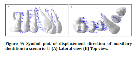
Figure 9. Symbol plot of displacement direction of maxillary dentition in scenario Ⅱ (A) Lateral view (B) Top view.
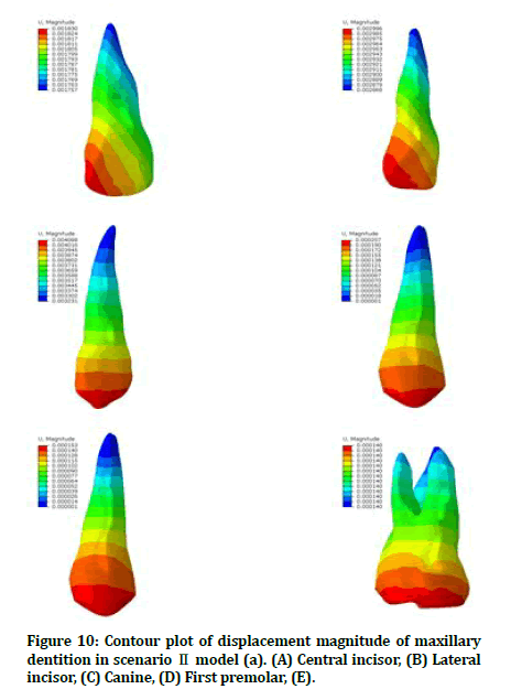
Figure 10. Contour plot of displacement magnitude of maxillary dentition in scenario Ⅱ model (a). (A) Central incisor, (B) Lateral incisor, (C) Canine, (D) First premolar, (E).
Canine
Displacement in the sagittal plane (ΔY): The canine tip distally in amount of (ΔY=1 to 2 μm).
Displacement in the transverse plane (ΔX): The canine have bodily movement toward the midline with magnitude of (ΔX=1 to 2 μm)
Displacement in the vertical plane (ΔZ): High magnitude of displacement of canine toward occlusal plane with tipping movement (ΔZ=-2 to -4 μm) (Table 3), and (Figure 9 and 10).
First premolar, second premolar, and first molar
This group of teeth show very small displacement in all direction (Figure 9 and 10).
Discussion
In scenario 1, the major tooth movement were in canine that tip distally by the action of distal vector of the force of the power chain or coil spring, in contrast, the mesial vector of the force will be distributed on the all teeth in the arch as they prepared to be work as one unit, and this force were far less than the optimal force of mesialization of full arch that reach 400 g [22]. But the force concentrated on first molar and cause intrusion and disto-buccal rotation of the first molar. This finding agree with [23] with keep magnitude difference [24], found that first molar intruded with mesial tipping and distobuccal rotation of first molar when apply a load at 30° to occlusal plan.
The first and second premolar were little mesialization by a force concentrated on first molar and this fact approved by present study that agree with other studies such as [24]. The incisors protruded as part of the full arch. The bodily movement were due to torque control by heavy gauge arch wire that agree with [24].
In scenario II the canine extruded with tipping palataly as the line of action of extrusion force were pass throw the crown away from the center of rotation of the tooth. This action accompanied by extensive intrusion and tipping of lateral incisor in spite of use of heavy gauge arch wire. This finding were agree with the engagement of continuous arch wire in a severely displaced canine [6].The central incisor also, intruded that lead to open bite formation, this agree with finding of [7].
The first and second premolar and first molar show very small displacement due to high anchorage demand of these teeth (high root surface area) this finding disagree with [25-32] who find that that the first premolars had the maximum anchor loss.
References
- Kraus BS. Dental anatomy and occlusion. 1st ed. Baltimore: Lippincott Williams & Wilkins; 1969.
- Nelson SJ, Ash MM. Wheeler’s dental anatomy, physiology and occlusion. 10th ed. St. Louis: Saunders An imprint of Elsevier Inc. 2015
- Ash MM, Ramfjord SP. Occlusion. 4th ed. Philadelphia: W.B. Saunders Co.; 1995.
- Nelson SJ, Ash MM. Wheeler’s dental anatomy, physiology and occlusion. 10th ed. St. Louis: Saunders An imprint of Elsevier Inc.; 2015.
- Ghaib NH, Buccally malposed maxillary canines a survey of school children aged 13-14 years. A master thesis, Department of POP, College of Dentistry, University of Baghdad. 1992
- Manhal SH. Buccally malposed mesially angulated maxillary canine management. Sebha University J Med Sci 2005; 4.
- Kim MJ, Park JH, Kojima Y, et al. A finite element analysis of the optimal bending angles in a running loop for mesial translation of a mandibular molar using indirect skeletal anchorage. Orthodont Craniofa Res 2018; 21:63-70.
- Vásquez M, Calao E, Becerra F, et al. Initial stress differences between sliding and sectional mechanics with an endosseous implant as anchorage: A 3-dimensional finite element analysis. Angle Orthodont 2001; 71:247-256.
- Cattaneo PM, Dalstra M, Melsen B. The finite element method: A tool to study orthodontic tooth movement. J Dent Res 2005; 84:428-433.
- Field C, Ichim I, Swain MV, et al. Mechanical responses to orthodontic loading: A 3-dimensional finite element multi-tooth model. Am J Orthodont Dentofac Orthop 2009; 135:174-181.
- Papageorgiou SN, Keilig L, Vandevska-Radunovic V, et al. Torque differences due to the material variation of the orthodontic appliance: A finite element study. Progress Orthodont 2017; 18:6.
- Papageorgiou SN, Sifakakis I, Keilig L, et al. Torque differences according to tooth morphology and bracket placement: A finite element study. Eur J Orthodont 2017; 39:411-418.
- Tominaga JY, Tanaka M, Koga Y, et al. Optimal loading conditions for controlled movement of anterior teeth in sliding mechanics. Orthodontic Waves 2010; 69:129-130.
- Duaibis R, Kusnoto B, Natarajan R, et al. Factors affecting stresses in cortical bone around miniscrew implants: A three-dimensional finite element study. Angle Orthodont 2012; 82:875-880.
- Lin CL, Yu JH, Liu HL, et al. Evaluation of contributions of orthodontic mini-screw design factors based on FE analysis and the Taguchi method. J Biomec 2010; 43:2174-2181.
- Kang JM, Park JH, Bayome M, et al. A three-dimensional finite element analysis of molar distalization with a palatal plate, pendulum, and headgear according to molar eruption stage. Korean J Orthodont 2016; 46:290-300.
- Park JH, Bayome M, Zahrowski JJ, et al. Displacement and stress distribution by different bone-borne palatal expanders with facemask: A 3-dimensional finite element analysis. Am J Orthodont Dentofac Orthop 2017; 151:105-117.
- Fattahi H, Ajami S, Rafsanjani AN. The effects of different miniscrew thread designs and force directions on stress distribution by 3-dimensional finite element analysis. J Dent 2015; 16:341.
- Gere JM, Timoshenko SP. Mechanics of materials, 3rd Edn. Nelson Thornes Ltd. 1991.
- Moga RA, Cosgarea R, Buru SM, et al. Finite element analysis of the dental pulp under orthodontic forces. Am J Orthodont Dentofac Orthop 2019; 155:543-551.
- Proffit WR, Fields HW, Msd DM, et al. Contemporary orthodontics. 6th Edn South Asia Edition-E-Book. Elsevier India, 2019.
- Elnagar MH, Elshourbagy E, Ghobashy S, et al. Dentoalveolar and arch dimension changes in patients treated with miniplate-anchored maxillary protraction. Am J Orthodont Dentofac Orthop 2017; 151:1092-1106.
- Wu JL, Liu YF, Peng W, et al. A biomechanical case study on the optimal orthodontic force on the maxillary canine tooth based on finite element analysis. J Zhejiang University 2018; 19:535-546.
- Kawamura J, Tamaya N. A finite element analysis of the effects of archwire size on orthodontic tooth movement in extraction space closure with miniscrew sliding mechanics. Progress Orthodont 2019; 20:3.
- Prasad KN, Mathew S, Shivamurthy P, et al. Orthodontic displacement and stress assessment: A finite element analysis. World J Dent 2017; 8:407–412.
- Ezzat KA, Kandil AH, Fawzi SA, et al. Determination of displacements in the biomechanical orthodontic system by using finite element method. Int J Applied Eng Res 2016; 11:6794-6799.
- del Castillo McGrath MG, Araujo-Monsalvo VM, Murayama N, et al. Mandibular anterior intrusion using miniscrews for skeletal anchorage: A 3-dimensional finite element analysis. Am J Orthodont Dentofac Orthop 2018; 154:469-476.
- Pol TR, Vandekar M, Patil A, et al. Torque control during intrusion on upper central incisor in labial and lingual bracket system-A 3D finite element study. J Clin Exp Dent 2018; 10:e20.
- Ryu WK, Park JH, Tai K, et al. Prediction of optimal bending angles of a running loop to achieve bodily protraction of a molar using the finite element method. Korean J Orthodont 2018; 48:3-10.
- Chae JM, Park JH, Kojima Y, et al. Biomechanical analysis for total distalization of the mandibular dentition: A finite element study. Am J Orthodont Dentofac Orthop 2019; 155:388-397.
- Yan W, Shao P. Three-dimensional finite element analysis on En mass intrusion and retraction of maxillary anterior teeth with J-hook headgear. Int J Clin Exp Med 2018; 11:9756-9761.
- Uysal C, Tuncer BB, Tuncer C. Maxillary posterior intrusion with corticotomy-assisted approaches with zygomatic anchorage-A finite element stress analysis. Progress Orthodont 2019; 20:8.
Author Info
Muthanna Ibraheem Ali1, Iman I Al Sheakli2* and Salah R Al Zaidee3
1Ministry of Iraqi health, Baghdad, Iraq2Department of Orthodontics, College of Dentistry, University of Baghdad, Iraq
3Civil Engineering, University of Baghdad, Iraq
Citation: Ali Ahmed Abbood, Thair A. Lateef Hassan, Treatment of Pediatric Mandibular Fractures Utilizing the Open Cap Splint: A Clinical Study, J Res Med Dent Sci, 2021, 9 (2): 43-51.
Received: 03-Jan-2021 Accepted: 19-Jan-2021
