Research - (2019) Volume 7, Issue 6
Stresses Induced in Dental Implant Retaining Screw before Tightening
Mohamed Tharwat Hamed1,2*, Hisham Abdullah Mously1, Abou Bakr Hosam Hashem3 and Ghada Hussein Naguib4,5
*Correspondence: Mohamed Tharwat Hamed, Faculty of Dentistry, Department of Oral and Maxillofacial Prosthodontics, Saudi Arabia, Email:
Abstract
Introduction: The tightening of the retaining screw helps in the insertion of implant at the mandible of first molar. Moreover, the calculation of the external loads acting on the screw head during its tightening and release need to be devised.
Aims: The study aims to predict the fatigue life of a retaining abutment screw used in dental implant.
Material and Methods: A typical straumann implant, inserted in place of missing first mandible molar was selected. 3D finite element stress analysis tool was used to evaluate the normal occlusion between the restoration crown and the opposing maxillary tooth. The mastication force acting mutually on the two teeth was simulated during the time of the occluding phase of the chewing process.
Results and Discussion: The fatigue damage parameter experienced at contact time was 206.5 ms by the most stressed site within the retaining screw that was plotted against the magnitude of the chewing force. The fatigue damage the parameter is below the Ti-6AI 4V threshold value for chewing force greater than 809 N. Findings of the study were provided considering the two assemblies consisting of Ti-6Al-4V titanium alloy, followed by type III gold of screws with the friction coefficient of each from the overall 14 values.
Conclusion: Considering the findings of the study, it is concluded that the release of the tightening moment of the wrench resulted in generating the equivalent stress. Results further concluded that the increase in coefficient friction on all the assembly parts resulted in the expansion of the stress followed by the increase in the wrenching tightening moment.
Keywords
Mandible, Dental implant, Screw tightening, 3D Finite element analysis, Von mises equivalent stress
Introduction
A tight connection between all assembly parts is established because of joint design of the dental implant. This generates enough resistance against the external forces. The tightening of the torque contributed in developing a strong resistance at the head of the screw, since it induces greater compression at different interfaces found between abutment and the screw head [1]. The corresponding threads of the implant and abutment screws shows similar signs of compression. The formation of low level of friction coefficient at the abutment screw was generated through the application of strong tightening leading towards a significant increase in preload found in the abutment screw [2]. The repeated closing and opening of screw joints result in reduction of friction coefficient through surface morphological changes [3].
The etiology of prosthetic complication is determined for analyzing the screw joints that are involved in the implant prosthodontics. The integrity of screw joint is maintained through the clamping force. Torque developed at the fastenings screw of the screw shrank resulted in the formation of tensile stress. The primary cause of screw breakage is the opening of screw joint between the cylinder and the abutment associated with its loosening [4]. The level of distortion is indicated through the measurement of strains in the implant frameworks. These measurements that were held at the simulated resin mandibles provide a similar association to the screw joints. Still, continuous measurements in relation to the screw joint preload failed to provide the interface level at the implant abutment [4]. This is because fabrication procedures are mainly focused through the classical implant prostheses along with the screw retention.
The present study aims to investigate the highest range of the von Mises equivalent stresses that are being generated at different locations of the assembly by inserting Straumann implants of different lengths ranging from ɸ 10mm to ɸ 4.1mm. The insertion of the given implants was held at the first molar of the mandibles, by tightening the retaining screws. The tightening and release of the screw head that helped in the developments of the external load were analyzed through different calculations undertaken during the increase or decrease of stress at the screw head. Therefore, investigations regarding the effectiveness of the Ti-6AI-4V abutment screw inserted during the dental implants taking place at the missing first mandible molar are undertaken in this study. The examinations are held considering the impact of loads developed due to the chewing cycle. Analysis regarding the formation of different magnitudes of the mastication force were also undertaken to provide the final threshold value for 15 years life.
Material and Methods
As stated above that the surface of the screw consists of the frictional moment. The advancement of the screw at the tightening phase is intervened through the development of axial forces. The implementation of 3D finite elements was held by utilizing the tightening loads. A comparative analysis between the linear stress strain and yield stress of the involved material were undertaken following the aim of developing maximum equivalent stress on each part of the implant assembly. The finite element analysis in relation to the axial forces acting on the inserted screw was held by providing relaxation to both frictional and wrench moments. The process was undertaken to compute the development of the residual stress, which itself serves as an important function of the friction coefficient.
Fa was analyzed by applying the turning moment M on the upper surface of screw head against the opposing force found parallel to the screw axis. The screw head consists of a helix angle α followed by the mean radius rmean. During the tightening of the screw, analogy for the frictional inclined surface of the screw thread was undertaken and is represented in Figure 1a. An angle α in the horizontal direction was formed, when the thread was horizontally folded following the circumference of the mean circle to form a thread. This thread was represented through an inclined surface making angle α there. Friction acting on the threaded surface of the screw was controlled by the application of moment Ms. A tangential force Ft was developed forcing the screw to move downwards at the inclined surface.
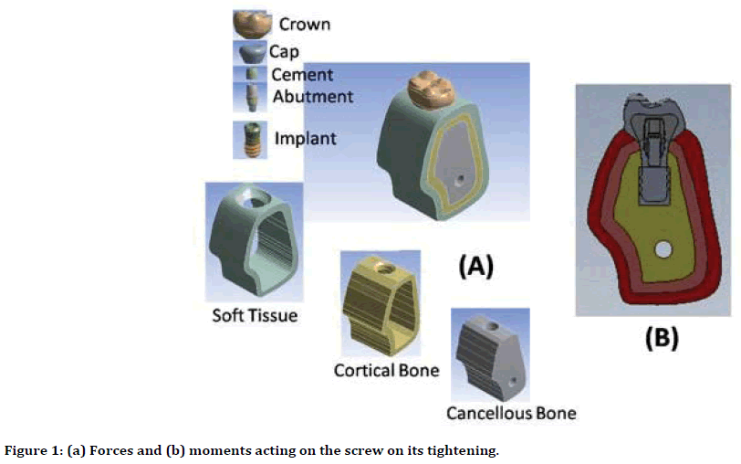
Figure 1. (a) Forces and (b) moments acting on the screw on its tightening.
Therefore,
Ms=ft.rmean (Equation 1).
In the above equation, R represents the reaction proposed by the nut thread surface on the surface region of the screw head. This reaction deviates from the upward normal direction to the inclined surface, following a friction angle μ
μ=tanф (Equation 2).
Forces including Ft, Fa, and R are now in equilibrium, therefore
Ft=Fatan(ф+α) (Equation 3).
Ms=Fa.rmean tan(ф+α) (Equation 4).
The moment applied on the top of the screw head, followed by the torque wrench must be given as Mc greater than Ms. Here, Mc represents the frictional moment found between the bottom surface of the screw head along with its contact surface with abutment (Figure 1b).
Mc=μ Fa.rmean (Equation 5).
In above equation, Rmean represents the mean radius of the contact area found between the abutment and the screw head. Then equation 6, can be given as
M=Ms+Mc=Fa[rmean] tan(ф+α)+μRmean(Equation 6).
The removal of Ms, Mc, and Ft takes place by the tightening of the wrench moment, while the screw is still in contact with the axial force Fa consisting its magnitude. At the opposite direction of the tightening moment, wrench was applied at the top of the screw head leading towards the untightening of the screw. The tightening moment is greater than the untightening moment. The directions of M, Ms, and Mc have been reversed, resulting in the upward movement of the screw on the inclined plane (Figure 1a). Therefore, it can be proved that Mu, which represents the untightening moment can be given as
Mμ=Fa[rmean tan(ф+α) μRmean (Equation 7).
Standard Ti-6AI-4V Straumann implant ranging in length from ɸ 4.1 mm wide and 12 mm was inserted at the place of the missing first mandible molar of an adult in a vertical manner. This resulted in the extension of bone and the soft tissues up to 14 mm at the local mesio distal direction. The sagittal- occlusal width of the bone was provided for approximately 11 mm. At the Ti-6AI-4V abutment to the implant, the retaining screw of Ti-6AI-4V was tightened with a suggested moment of 0.3 nm. Following this, the cementation of the tailored type III gold cap was held, that was bonded to the porcelain crown considering the overall geometry of first molar of the mandible. The ANSYS release 13.0 FEA software was used to attain a three-dimensional geometry of the model.
A 3D geometrical idealization was constructed through a solid works premium 2010 SP0.0 for the normal implant of Ti-6Al-4V Straumann with its length ranging between the ф 4.1 mm and 12 mm. The attained occlusal width of the sagittal bone was considerably 11 mm. Different considerations regarding the geometry of cortical bone, cancellous bones and mucosa were undertaken following the exact proportion. The core cancellous bone was surrounded by the cortical bone with a total thickness of approximately 2 mm. The implant axis coincided with the occlusal table’s central point. After the osseointegration, a standard Ti-6Al-4V abutment to the implant was fixed by the retaining screw. The top surface of the screw head was further providing the tightening moment that was monotonically applied following the ramp manner. Wrench moment was then released after the tightening. An analysis of the stressdeformation concerning the 3D finite element was undertaken. This is due to the stress generated within the system of implant tissue, followed by the release of the wrench tightening moment. The attempt for the available failed implant was undertaken to utilize the fixed dimensions of the abutment, implant and the screw. The isometric view of the of the model following the sagittal cross section is presented in Figure 2. The final mesh idealization was generated by ANSYS, consisting the growth rate of 1.2 with smooth transitions (as indicated in Figure 2). The mesh consists of the 103928 tetrahedral elements and 180398 nodes. Depending upon the total energy of the elasticity strain, advanced mesh trials were exercised to develop a conversion with a final mesh. Table 1 of this study indicates the used materials’ mechanical properties.
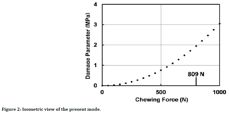
Figure 2. Isometric view of the present mode.
| Material | Elasticity modulus GPa |
Poisson’s ratio |
|---|---|---|
| Titanium alloy Ti-6Al-4V | 117 | 0.33 |
| Type III Gold | 100 | 0.33 |
| Cortical Bone | 14.7 | 0.3 |
| Cancellous Bone | 0.49 | 0.3 |
| Soft Tissue | 1.18 × 10⁻³ | 0.45 |
Table 1: Mechanical properties of the materials for the analyzed models.
The central surface of the corticla bone was fixed following the mesiodistal displacements of distal and mesial planes. The contact surfaces of different parts of the assembly were restricted to separation. The assumptions regarding the contact surfaces of the screw with both implant and the abutment were undertaken. The analysis provided in the previous section was undertaken to load the screw head for simulation of screw tighteneing following the release of the wrench moment. Figure 1b has shown the screw with the three loads, i.e. the first is related to the tightening moment following the suggested value of M at the top surface of screw. Second is related to the frictional contradicting moment Mc formed at the contact bottom surface of screw (see Equation 5). Final load is associated to the axial force Fa developed at the contact bottom surface of the screw that resists the screw advancement during the tightening phase (as indicated in Equation 6). Both M and Mc were monotonically unloaded to leave Fa acting only on the screw head to release the wrench moment.
The analysis related to the given screw materials i.e. type III gold and Ti-6Al-4V titanium alloy was undertaken. The following values of M (30 N cm and 20 N cm) for both the titanium screw and the gold screw were provided respectively. 14 different values of μ ranging from 0-2 were considered in this study. With the present screw dimensions, Equations (6) and (5) calculated both Fa and Mc for the two screw materials with each μ value. For each value of μ, analysis of the linear elastic stress deformation was undertaken. Overall 14 analyses were undertaken for every screw material involved in this study. The problem was solved by using the interactive technique of ANSYS to cater the problem. The analysis resulted in the computation of the increased von Mises equivalent stress eqn that was left in every single component of the assembly. The yield stress of the material was compared to the tightening procedure.
Results
The fatigue damage parameter experienced at contact time=206.5 by the most stressed site within the retaining screw and plotted against the magnitude of the chewing force; fatigue damage parameter is below the Ti-6AI-4V damage parameter is below the Ti-6AI-4V threshold value for chewing force <809N. Figure 3 provides the impact of μ on Mc (frictional moment) found between the bottom surface of the screw head along with the contact surface of the screw with abutment. These results are indicated for type III gold and Ti-6Al-4V titanium alloy screws. The friction formed at the head surface of the screw was controlled by the differences between wrench turning moment that was applied on the M and Mc found at the top surface of the screw. A constant value of μ>0.5 was achieved for both the screw materials, as according to the results the increase in Mc increases the increase in μ. A significant decrease in μ was recorded in the moment that is available to reduce the thread friction, to attain the constant value in comparison to the maximum values of μ. For gold screw, both Mc and Ms values decreased for all values equal to μ=0 that are less in comparison to the corresponding values attained for the titanium screw.
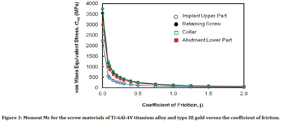
Figure 3. Moment Mc for the screw materials of Ti-6Al-4V titanium alloy and type III gold versus the coefficient of friction.
Figure 4 provides the axial pressure Pa of tightening, against μ for both gold and titanium screws. A high value of Pa was attained in the beginning with the given value of μ=0, which then decreases by the increase in μ=0 providing the constant values at μ. For gold screw, the Pa magnitude was less in comparison to the corresponding values of the titanium screw for each value of μ. Figure 5 indicates the variation of the increased von Mises equivalent stress σeq, that was affected by the metallic parts of the existing model. This was particularly provided for titanium retaining screw. Figure 5 consists of the titanium alloy that represents the materials of four different parts. Metallic parts that are not represented in Figure 5 represents the minimum stress at different μ values. In Four parts that are presented in Figure 5, σeq begins with the maximum value at μ=0, which then continuously decreased by the increase in μ. At the maximum μ values, a descending arrangement was followed at the generated stress values. This is due to the reason as upper implant consists of the retaining screw, lower part of the abutment and screw collar. The arrangement is dissimilar at particularly low values of μ, in cases where maximum stress was taking place at the screw collar, and minimum stress on upper part of implant.
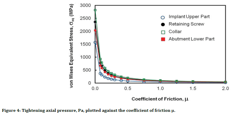
Figure 4. Tightening axial pressure, Pa, plotted against the coefficient of friction μ.
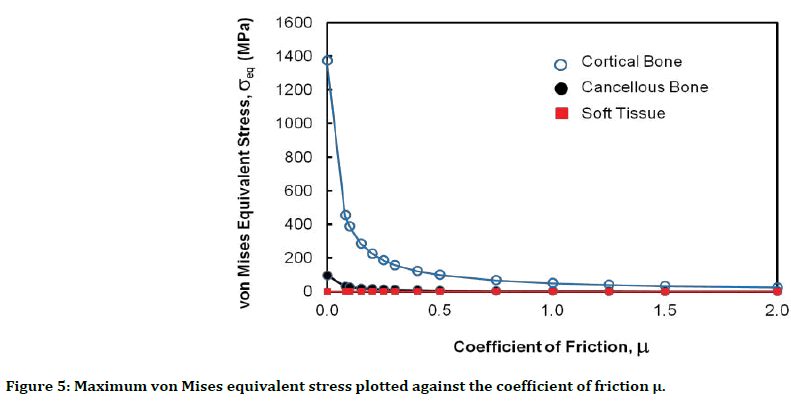
Figure 5. Maximum von Mises equivalent stress plotted against the coefficient of friction μ.
The following three points have been observed in relation to the effect of the release of the wrench tightening moment on the stress fields within the implant assembly/tissue system. First, there was no impact on the stress field within the bone and soft tissues for all μ values. The coefficient of friction influenced the stress field within the metallic assembly at relatively low μ values with a continuously decreasing effect.
Discussion
The reduction in friction coefficient is likely to increase stress within the implant-abutment complex leading to deformation of plastic during its loading at the implant neck. The stability attained between the implant and the abutment determines the success criteria of the restorative treatment [5]. This stability is likely to be jeopardized due to loosening of the screw, including the excessive abutment-implant. In certain cases, the abutment screw loses with in the period of about 8-10 years. Theoharidou et al. [6] conducted a study and indicated that approximately 2.4% of screw loosening was found in the internal connection, and 2.7% at the external connection of implants. Screw loosening is inhibited by screw preload that is defined as an important mechanical factor. The strength of preload depends on design of the abutment screw, tightening torque, design of abutment-implant connection, and lubrication [7]
The present study has clearly depicted certain forces that are constantly applied to the abutment screw. Mohammad et al. [7] conducted a study, according to which forces like cantilevered occlusal contacts, non-passive fit of the restoration, lateral excursive contacts, parafunctional habits, and tight interproximal contacts are applied to the abutment screw. External forces exceeding the screw joint preload results in unstable joint. Slippage between the threads is caused because of continuous functional loading resulting in decreased tension and decreased preload. The function subsides when preload falls below the demanding value and the screw threads turn due to application of external force [8]. In addition, Delben et al. [9] proposed that minimum level of torque is required in removing the screw in comparison to the level of torque required during the screw tightening. Therefore, to increase the level of preload, it is recommended to tighten the abutment screws.
Like the present study, another study conducted by Tan and Nicholls [4] reported the screw joint preload that is achieved due to tightening of screws. The levels of screw preload joint indicate the maintenance of screw joint integrity during clinical performances. These levels are achieved at different abutment systems. Another study conducted by Jorn et al. [1] depicted that decrease in coefficient friction tend to increase the screw preload. Moreover, the stresses increase as there was decrease in the friction coefficient. However, there was no plastic deformation of the abutment. The results also showed screw preload is associated with finite element analysis of the dental implants for evaluating the stresses in implant-abutment complex [1]. Within the implant-abutment complex, the friction coefficient is significantly affected by the screw preload value and modified stresses.
Conclusion
The average life for an implant is infinite if the chewing force below 800N. Studies in relation to the internal and external hex implants joint stability are important to prevent the maximum consumption of time and efforts involved during screw tightening of the longer abutment screws. The central aim of this study was to predict the fatigue life of a retaining abutment screw that is generally used during the dental implant. Moreover, the study has investigated integrity of Ti-6AI-4V abutment screw of a dental implant replaces first mandible molar due to loads approaching typical service chewing cycle with different magnitudes of mastication force. The results have clearly shown that equivalent stresses are likely to be generated after wrench tightening, which increases the friction coefficient. There is detrimental effect of friction on stresses in the implant components during the assembling of implant and abutments. The study results recommend shortening of the abutment screw length for preserving the problem and simplify its manipulation. The future studies are recommended to focus on clinical longevity during the implant-abutment connections.
Acknowledgments
The author is highly thankful to all the associated personnel that contributed completion of this study. Further, this research holds no conflict of interest.
References
- Jörn D, Kohorst P, Besdo S, et al. Influence of lubricant on screw preload and stresses in a finite element model for a dental implant. J Prosthet Dent 2014; 112:340-348.
- Benac DJ. Technical brief: Avoiding bolt failures. J Failure Analy Prevent 2007; 7:79-80.
- Guzaitis KL, Knoernschild KL, Viana MA. Effect of repeated screw joint closing and opening cycles on implant prosthetic screw reverse torque and implant and screw thread morphology. J Prosthet Dent 2011; 106:159-169.
- Tan KB, Nicholls JI. Implant-abutment screw joint preload of 7 hex-top abutment systems. Int J Oral Maxillofac Implants 2001; 16:367-377.
- Cibirka RM, Nelson SK, Lang BR, et al. Examination of the implant-abutment interface after fatigue testing. J Prosthet Dent 2001; 85: 268-275.
- Theoharidou A, Petridis HP, Tzannas K, et al. Abutment screw loosening in single-implant restorations: A systematic review. Int J Oral Maxillofac Implants 2008; 23:681-690.
- Mohammed HH, Lee JH, Bae JM, et al. Effect of abutment screw length and cyclic loading on removal torque in external and internal hex implants. J Adv Prosthod 2016; 8:62-69.
- Tsuge T, Hagiwara Y. Influence of lateral-oblique cyclic loading on abutment screw loosening of internal and external hexagon implants. Dent Mater J 2009; 28:373-381.
- Delben JA, Gomes EA, Barão VA, et al. Evaluation of the effect of retightening and mechanical cycling on preload maintenance of retention screws. Int J Oral Maxillofac Implants 2011; 26:251-256.
Author Info
Mohamed Tharwat Hamed1,2*, Hisham Abdullah Mously1, Abou Bakr Hosam Hashem3 and Ghada Hussein Naguib4,5
1Faculty of Dentistry, Department of Oral and Maxillofacial Prosthodontics, Saudi Arabia2Department of Fixed Prosthodontics, School of Dentistry, Cairo University, Egypt
3Dental Department, Research institute of Ophthalmology, Giza, Egypt
4Faculty of Dentistry, Department of Restorative Dentistry, Saudi Arabia
5Faculty of Dentistry, Department of Oral Biology, Cairo University, Egypt
Citation: Mohamed Tharwat Hamed, Hisham Abdullah Mously, Abou Bakr Hosam Hashem, Ghada Hussein Naguib, Stresses Induced in Dental Implant Retaining Screw before Tightening, J Res Med Dent Sci, 2019, 7(6): 33-39.
Received: 05-Sep-2019 Accepted: 05-Nov-2019
